
With the proliferation of microcontroller development boards from which to choose, one seems to get shafted - the Texas Instruments MSP430 Value Line. At less than $10, this little board (or IC if you're like me and prefer going with the basics) is a Godsend! It has been my go-to-processor of late, and with my new found love of building unique clocks, I knew that it was just waiting to be paired with a few Nixie tubes.
As always, my projects are based on parts that I have on hand. Sometimes that means that they are a little difficult to duplicate for the average user, but I hope that I will provide enough information in the following paragraphs to overcome that little obstacle.
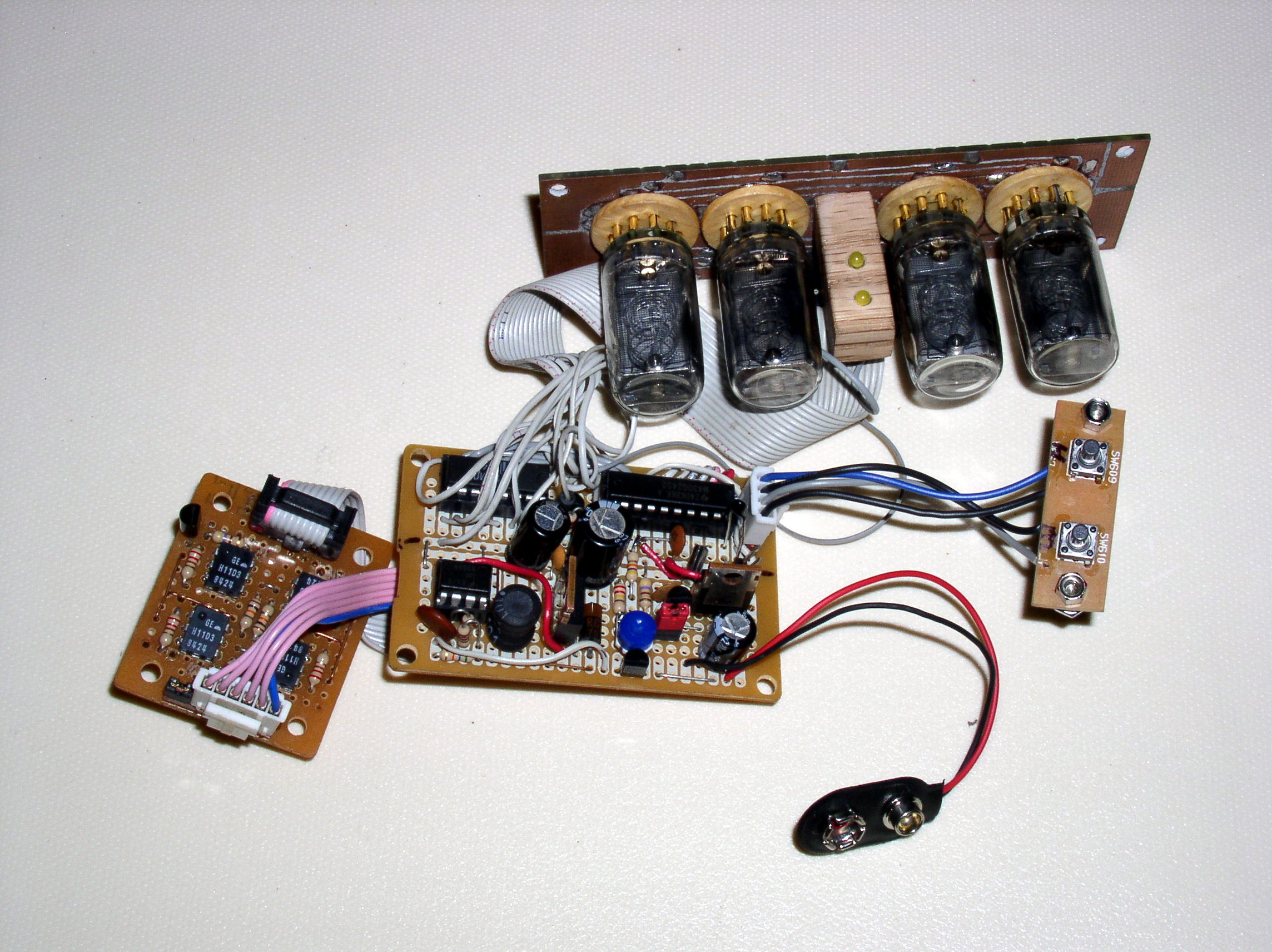
In addition to the MSP430, you'll also need a Russian SN74141N decoder/driver, a 555 timer, four H11D3 optocoupler/isolators, a 500Ω thermistor and the main star of the project - four NL904 inverted Nixie tubes, along with the handful of support components.
Nixie tubes need ~170vDC to fire. Since the current needed is extremely low (3.5mA max for the NL904), we can derive this from the 12 volt power supply using a step-up boost switchmode circuit. Rather than reinvent the wheel, I used the circuit found here nixie_supply.pdf. I will leave it to the author of this circuit (the article does not provide a name) to explain it's operation.
With sockets for Nixie tubes being hard to come by, I had to custom make the board complete with makeshift sockets. The pins of the "sockets" are salvaged from DB25 connectors and soldered to the board. Works great! Schematics (in PNG, PDF and Eagle CAD formats)including scans of the Nixie tube display board can be downloaded here - schematics.zip.
The code (available here - code.zip) is heavily documented and should be self-explanatory. Basically, the nixie tubes are multiplexed to reduce the number of pins and ICs needed. Every 10 seconds, the display switches from time display to temperature display and back. Just like in my Coffee Pot Fish tank, the temperature is sensed using an NT03-50169 500 ohm temperature sensor R1 in a standard voltage divider configuration. This is fed to the MSP's built-in ADC and, using a look-up table (calculated using values found in the device datasheet plugged into python script createTemperatureLookup.py), is converted to a temperature in Fahrenheit.
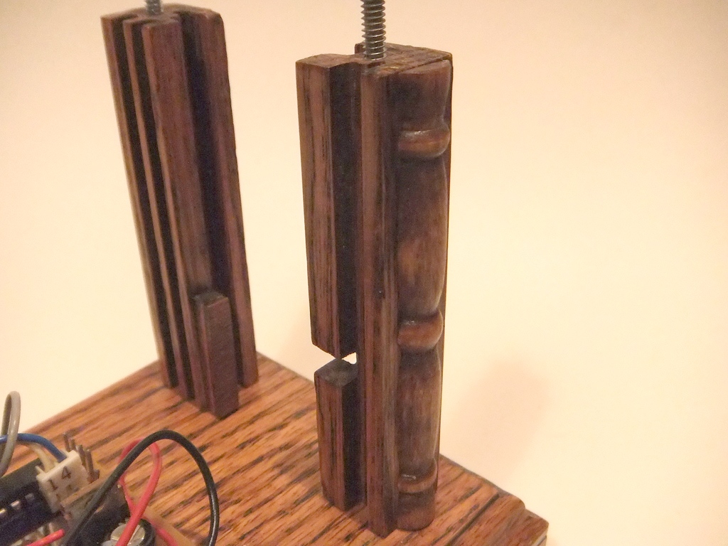
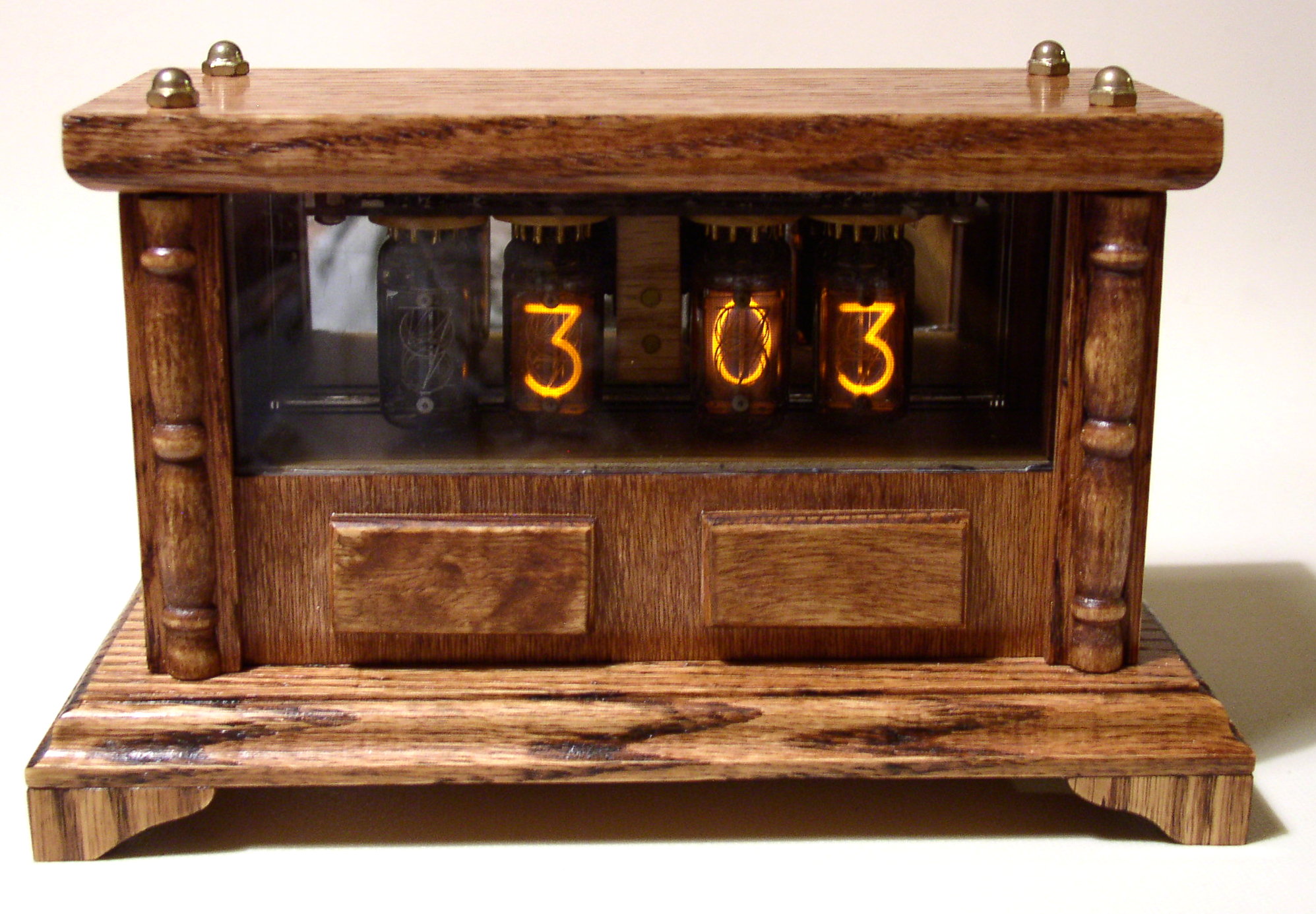
The case consists of four pillars with panels all around - completely modular including a mirror behind the tubes and plexiglass in front. Templates and Sketchup designs for the case can be downloaded here - templates.zip. The templates are drawn full scale, so when you print them out, make sure that zoom is set to 100% and that resize is turned off.
For a complete set of plans including all schematics, datasheets, templates, software code and project photos, click here - nixie.clock-MSP.zip.
These plans are, like the other projects offered here on my site, completely free for your own personal use. All I ask is 1) that you do not sell these plans or the completed projects; and B) if you modify any portion of the plans, schematic or code that you give credit where credit is due - as I have for the sources I used. Also, if you do make any changes or build your own, I would love to see photos or hear about it. And if you feel so inclined to make a small donation, please don't let me stop you :) You can find a donation button at the bottom of the main page: www.RobotsAndComputers.com